|
|
Ford Motor Co.
- 1996 Excellence Award Winner
Stereolithography has been utilized heavily for 'touch and feel' since its creation. Over the past ten years, applications have expanded to include development of rapid tooling and casting processes. At Ford Motor Company's Advanced Vehicle Technology division, efforts have been underway for several years to expand the use of stereolithography to include experimental stress analysis for the purpose of design validation and correlation of FEA.
A variety of methods for accomplishing this have been developed, and they are collectively referred to as 'Rapid Stress Analysis (RSA). By utilizing stereolithography and RSA, engineering designs can be experimentally validated months earlier than was previously possible and at much lower cost. Typical cost savings of using SL prototypes rather than conventional prototypes range from a few thousand dollars to tens of thousands of dollars, depending on the complexity of producing and testing the prototype via conventional processes.
Predicting critical stress regions in exhaust manifolds remains a challenging problem. In order to use CAE modeling techniques such as Finite Element Analysis, accurate boundary conditions must be known, including the temperature distribution and heat conduction/convection characteristics of the exhaust manifold, engine block and exhaust gases. Furthermore, the complex 3-dimensional shapes of exhaust manifolds require sophisticated and time-consuming finite element modeling techniques.
It was realized early in 1995 at Ford that stereolithography could again come to the rescue. By using an SL prototype exhaust manifold mounted on a motoring engine, most essential boundary conditions needed to perform experimental photoelastic stress analysis could be obtained.
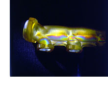
A SL 5170 stereolithography prototype exhaust manifold was mounted to a motoring engine in order to maintain exhaust temperatures that were hot enough to induce thermal stresses in the SL prototype, but not so hot as to destroy the prototype. The inside of the exhaust manifold was coated with a thin layer of reflective paint to allow polarized light to pass through the skin thickness of the manifold and then be reflected back out. As the polarized light is passing through the SL prototype, it will experience additional polarization depending on the magnitude of the stresses at that location. The larger the stresses, the greater the degree of polarization. A photoelastic polariscope was used to monitor the resulting colored fringes that occurred at the critical stress locations. These critical stress locations measured with a SL 5170 prototype were in excellent agreement with regions that experienced thermal fatigue cracking on exhaust manifolds tested on running engines.
Using SL prototypes to determine critical thermal stress regions on prototype exhaust manifold designs eliminates months from the design validation process. Traditional methods require the creation of a prototype metallic exhaust manifold followed by long-term durability testing -- a process typically requiring three to six months. By using stereolithography prototypes combined with the Rapid Stress Analysis process, the same useful information (i.e., the critical thermal stress regions) was obtained in less than a week from the completion of CAD modeling.
|
|
|
 With concept-to-customer timing continuously shrinking
in the automotive industry (and most other engineering industries as well),
the need to rapidly validate engineering designs is becoming ever more critical.
It is no longer acceptable to design a component, produce soft tooling,
build and test a prototype, analyze what failed, and then redesign. Instead,
heavy use is being made of advanced CAE methods, such as Finite Element
Analysis (FEA). Even so, FEA is only a tool, and rapid methods to experimentally
validate FEA are needed.
With concept-to-customer timing continuously shrinking
in the automotive industry (and most other engineering industries as well),
the need to rapidly validate engineering designs is becoming ever more critical.
It is no longer acceptable to design a component, produce soft tooling,
build and test a prototype, analyze what failed, and then redesign. Instead,
heavy use is being made of advanced CAE methods, such as Finite Element
Analysis (FEA). Even so, FEA is only a tool, and rapid methods to experimentally
validate FEA are needed.